
Relocating Overhead Cranes: Safe Dismantle to Recommission
Ernest Parfentiev · Founder & Managing Director, NM SOLUTIONS
Overhead travelling cranes and gantry systems are among the most demanding assets to relocate. They live high above the shop floor, carry heavy hoists and drives, run on precision-aligned rails, and are safety-critical lifting equipment governed by strict inspection rules. Moving one is never just a lift — it is a structured dismantling and reinstallation project where geometry, structural loads and legal compliance all matter. This guide walks through how experienced teams plan and execute a crane relocation from first survey to load test.
Why Crane Relocations Are Different
Unlike a standalone machine, an overhead crane interacts with the building itself. The runway rails sit on crane beams supported by the structure, so any move affects — and is affected by — the host building at both origin and destination. Key characteristics that shape the project:
- Working at height: most dismantling and installation happens on elevated runways, requiring fall-protection and controlled access.
- Precision alignment: span, rail gauge, level and straightness must fall within tight tolerances or the crane will bind, skew and wear prematurely.
- Heavy, awkward components: main girders can be long and slender, prone to twist and buckling if lifted incorrectly.
- Legal status as lifting equipment: after reinstallation the crane must be re-inspected and load-tested before it returns to service.
Phase 1: Survey and Engineering
Every successful relocation starts with a detailed site survey at both locations. Document the crane's key data: capacity, span, lift height, number of hoists, power supply (busbar or festoon), control system and end-of-travel arrangements. Capture the runway geometry, beam sections and how the rails are fixed.
At the destination, confirm the receiving structure can carry the crane's wheel loads, including impact and dynamic factors. If the building was not originally designed for a crane, an independent structural check is essential — never assume existing steelwork is adequate.
Deliverables from this phase
- A dismantling and rigging plan with lift weights and centres of gravity.
- A method statement and risk assessment covering work at height and lifting operations.
- A component list with match-marking scheme so everything returns to its original relative position.
- A destination readiness checklist (runway, power feed, clearances, access for cranes).
Phase 2: Isolation and Preparation
Before any component comes down, the crane must be fully de-energised and isolated. Apply lockout/tagout to the main disconnect and any control circuits, and verify zero energy. Park the trolley and bridge in accessible positions and lower the hoist blocks.
Preparation typically includes:
- Draining or securing any hydraulic or lubrication systems.
- Disconnecting and labelling power feeds, festoon cables or busbar collectors.
- Recording rail alignment data (span, level, straightness) as a reference baseline.
- Protecting sensitive items — controls, encoders, VFD panels, radio remotes — against dust and impact.
Match-marking is critical here. Number each rail clamp, bolt group, drive assembly and electrical connection so reassembly is unambiguous rather than guesswork.
Phase 3: Dismantling
Crane dismantling reverses the erection sequence and demands strong lifting resources — usually mobile cranes positioned outside the building or working through roof openings, sometimes gantries or strand jacks inside.
A typical order of removal:
- Remove the hoist and trolley (or crab), keeping the wire rope and reeving documented.
- Detach drives, panels, festoon and end trucks as sub-assemblies where practical.
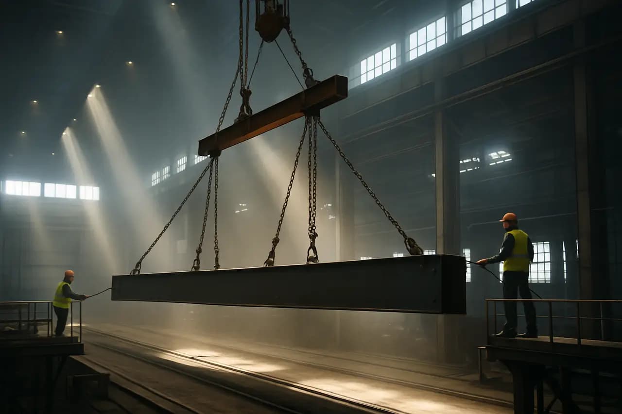
- Lift the main girder(s). Long girders need spreader beams and correctly placed lifting points to avoid bending or twisting; a lift plan should confirm sling angles and stresses.
- Remove runway rails only if the entire system, including beams, is being relocated.
Throughout, control exclusion zones on the floor below, use tag lines to steady loads, and never allow personnel under a suspended load. Slender girders should be supported to prevent permanent deformation during handling and transport.
Phase 4: Packing and Transport
Girders are long, heavy and often exceed standard trailer dimensions, so plan transport early. Depending on length and weight the move may require extendable trailers and, for the largest spans, an over-dimensional permit and route survey across Europe.
Good practice for transport:
- Support girders on cradles at correct points to avoid sagging or twist.
- Crate or wrap drives, hoists and electrical assemblies against weather and vibration.
- Bundle and label fasteners, small parts and cable ends so nothing is lost.
- Secure loads to recognised lashing standards and account for the girder's flexibility.
Phase 5: Reinstallation and Alignment
At the destination, install or verify the runway first. The two rails must be correct for span, level, straightness and elevation difference — the crane manufacturer's tolerances are the reference. Even small deviations cause skewing, flange wear and increased power draw.
Reassembly then follows the reverse of dismantling: place the girders, refit end trucks and drives, reinstall trolley and hoist, then reconnect power and controls. Torque all structural bolts to specification and record the values. Reconnect the power supply — busbar or festoon — and dress cables so they travel freely across the full range of motion.
Alignment checks that matter
- Span and gauge: measured at several points along the runway.
- Wheel contact and skew: all wheels should share the load; check for gaps.
- Level and rail joints: smooth transitions prevent shock loading.
- End stops and limit switches: correctly positioned and functional.
Phase 6: Recommissioning and Load Testing
A relocated crane is legally a piece of lifting equipment being put back into service, so it must be inspected and tested before use. Recommissioning typically includes:
- Functional checks of all motions, brakes, limit switches and safety devices (overload protection, anti-collision, emergency stop).
- A no-load run across the full travel to confirm smooth, skew-free operation.
- A static and dynamic load test at the prescribed overload percentage, witnessed and documented.
- Verification of the safe working load marking and updated inspection records.
Have a competent person carry out the thorough examination and issue the report. Only after satisfactory results and sign-off should the crane return to production.
Common Pitfalls to Avoid
- Underestimating structural loads at the new building — always verify capacity, not just clearance.
- Skipping the baseline alignment survey, which removes any reference for correct reassembly.
- Lifting girders from the wrong points, risking permanent deformation.
- Neglecting cable management, leading to festoon snags or busbar arcing.
- Returning to service without a documented load test and current examination report.
The Takeaway
Relocating an overhead crane rewards early engineering and disciplined execution. Treat it as a structural, mechanical, electrical and compliance project rolled into one: survey thoroughly, respect the geometry, protect the components in transit, and never bypass load testing and inspection. Done properly, the crane returns to service reliably — aligned, safe and ready to lift for years to come.
Related
Ernest Parfentiev
Founder & Managing Director, NM SOLUTIONS
NM Solutions specializes in the dismantling, relocation, installation and commissioning of industrial equipment and production lines across Europe — with hands-on project experience in metallurgy, food, packaging and building-materials plants.